The hydro generator is the heart of every hydropower plant — yet it remains one of the least explained components in engineering literature online. Search for hydropower content and turbines dominate every result. Generator explanations are generic, shallow or simply absent. This guide fills that gap — covering everything an engineer needs to understand about hydro generators, written from 15 years of field experience commissioning generators on some of the world’s largest hydropower projects.
What is a Hydro Generator?
A hydro generator is a synchronous electrical machine that converts mechanical rotational energy from a hydraulic turbine into three phase alternating current electricity. It is the final energy conversion step in the hydropower generation chain — water energy becomes mechanical energy in the turbine, mechanical energy becomes electrical energy in the generator. The generator produces electricity at medium voltage — typically between 6.6kV and 22kV depending on unit capacity and design.
The optimal voltage range for large hydro generators falls between 11kV and 18.8kV — a balance between insulation requirements and copper losses. Higher generation voltage reduces stator current for the same power output, directly reducing I²R copper losses in the stator windings and improving overall generator efficiency. This voltage is then stepped up by the main power transformer — also called the generator transformer — for transmission to the grid at 132kV, 220kV or 500kV depending on the project. Unlike thermal generators which are driven by steam turbines at fixed high speeds, hydro generators operate across a wide range of speeds depending on the hydraulic head and turbine type of each specific project.

How Does a Hydro Generator Work?
The operating principle of a hydro generator is electromagnetic induction — the same fundamental principle discovered by Michael Faraday in 1831. A rotating magnetic field cuts through stationary conductors and induces an electromotive force — voltage — in those conductors. In a hydro generator the rotating magnetic field is created by the rotor — energized by direct current flowing through its field windings. The stationary conductors are the stator windings — three sets of coils arranged 120 degrees apart around the inner circumference of the stator core. As the rotor spins, its rotating magnetic field sweeps past each stator winding in sequence — inducing three alternating voltages displaced 120 degrees from each other in time.
This is three phase alternating current — the standard electrical output of every hydro generator worldwide. The frequency of this AC output is determined by two factors — the rotational speed of the rotor and the number of magnetic poles on the rotor.

The Synchronous Speed Formula — N = 120f/P
Every hydro generator must produce electricity at exactly the grid frequency — 50Hz in most of Asia, Africa, Europe and Australia, 60Hz in North America. The relationship between synchronous speed, frequency and pole number is expressed by:
N = 120f / P
Where N is synchronous speed in revolutions per minute, f is grid frequency in Hertz and P is the number of magnetic poles on the rotor. This formula is the starting point for every hydro generator design. The turbine designer first calculates the optimal runner speed for maximum hydraulic efficiency at the specific head and flow of the project site. The generator designer then calculates how many poles are needed to produce exactly 50Hz at that turbine speed. The two designs are inseparable — turbine and generator are engineered together as a perfectly matched unit. A generator cannot be specified without knowing the turbine speed. A turbine cannot be finalized without knowing the generator pole configuration. This interdependence is one of the defining characteristics of hydro unit design that distinguishes it from all other generation technologies.
Pole Numbers and Speed — Real Engineering Examples
The number of poles on a hydro generator rotor varies significantly depending on project characteristics. Unlike thermal generators which typically run at 3000 RPM with 2 poles or 1500 RPM with 4 poles, hydro generators span an enormous speed range:
| Poles | Synchronous Speed (50Hz) | Typical Application |
| 4 | 1500 RPM | Small high head Pelton |
| 8 | 750 RPM | Medium head Pelton |
| 12 | 500 RPM | High head Francis |
| 16 | 375 RPM | Medium-high head Francis/Pelton |
| 24 | 250 RPM | Medium head Francis |
| 32 | 187.5 RPM | Low-medium head Francis |
| 40 | 150 RPM | Low head Kaplan |
| 60 | 100 RPM | Very low head Kaplan |
| 72 | 83.3 RPM | Ultra low head Bulb turbine |
A 16 pole generator operating at exactly 375 RPM synchronous speed— illustrates a fascinating engineering reality. Two completely different turbine types at completely different hydraulic heads can both drive an 16 pole generator at 375 RPM. A Pelton turbine at high head and a Francis turbine at medium head can both be designed to achieve peak hydraulic efficiency at 333 RPM — arriving at the same synchronous speed through completely different hydraulic design paths, both matched to the same generator pole configuration for 50Hz generation. The turbine runner diameter, jet size and bucket geometry for the Pelton — or the spiral casing, runner diameter and blade angle for the Francis — are all optimized around this single synchronous speed requirement. This is the engineering elegance of hydro unit design.
Main Components of a Hydro Generator
1. The Stator
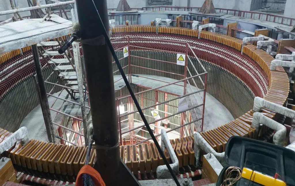
The stator is the stationary outer component of the generator — a massive cylindrical structure of laminated electrical steel carrying the three phase armature windings. Stator laminations — thin sheets of grain oriented silicon steel — are used instead of solid steel to minimize eddy current losses caused by the rotating magnetic field. The stator core is assembled from thousands of individual laminations bolted together and mounted in the stator frame. Slots machined into the inner circumference of the stator core hold the armature windings — copper conductors insulated to withstand the full generator terminal voltage continuously throughout the plant’s operational life. The stator winding is distributed in three phases — Phase A, Phase B and Phase C — arranged in slots around the stator bore and connected in star configuration at the generator neutral point.
Field Fact — A detail that surprises most people outside the industry: hydro generator stators are never delivered to site as complete assembled units. The sheer weight of a large hydro generator stator — reaching 450 tonnes on major projects — makes factory assembly and transportation to remote mountain project sites physically impossible. Instead stator laminations, core segments, frame sections and windings are manufactured separately, transported to site in manageable components and assembled in the generator hall by specialized erection teams. The generator hall itself is designed around this assembly process — crane capacity, floor loading, access routes and lay down areas all sized for stator assembly on site. This site assembly process requires exceptional precision — the assembled stator must meet dimensional tolerances measured in fractions of a millimetre despite being built from thousands of individual components in field conditions.
2. Rotor
The rotor is the rotating component of the generator — mounted on the main shaft and directly coupled to the turbine runner below. Hydro generators predominantly use salient pole rotors — rotors with individual projecting poles mounted around a central spider structure. Each pole carries a field winding — coils of copper conductor wound around the pole body and connected in series around the rotor circumference. Direct current energizes these field windings through slip rings on the rotor shaft — creating the rotating magnetic field that induces voltage in the stator windings.
The number of salient poles determines the synchronous speed as described by the N = 120f/P formula. Large hydro generators may have rotor diameters exceeding 15 metres and weights exceeding 1000 tonnes — making rotor installation one of the most technically demanding operations in hydro plant construction. Rotor assembly tolerances are measured in fractions of a millimetre despite these enormous physical dimensions.
Field Fact — Like the stator, the rotor is assembled entirely on site. Individual rotor poles, the spider structure, rim segments and shaft are all transported separately and assembled in the generator pit. Rotor assembly is a critical path activity on any hydro project schedule — delays in rotor erection directly delay first generation. The rotor spider — the central structural framework supporting all poles — is typically the heaviest single component and defines the assembly sequence. Poles are installed one by one around the spider, each aligned and torqued to exact specification. The completed rotor assembly weight on large units matches or exceeds the stator — making the generator hall floor slab and foundation one of the most heavily loaded civil structures on the entire project.
3. The Main Shaft
The main shaft transmits mechanical torque from the turbine runner to the generator rotor. In vertical shaft hydro generators — the predominant configuration for medium and large hydro plants — the shaft is a massive steel forging connecting the turbine runner at the bottom to the generator rotor above. Shaft alignment is critical — misalignment causes vibration, bearing damage and premature wear on both turbine and generator components. Shaft alignment verification is one of the most important pre-commissioning activities on any hydro unit. Even fractions of a millimetre of misalignment at the coupling flanges translates into significant vibration at operating speed — vibration that accelerates bearing wear, fatigues mechanical connections and ultimately reduces plant availability and operational life.
4. The Bearings
Three types of bearings support the rotating components of a vertical shaft hydro generator. The thrust bearing — typically located at the top of the generator — carries the entire weight of the rotating assembly including turbine runner, shaft and rotor, plus hydraulic thrust forces from water pressure on the turbine runner. This is one of the most highly loaded bearings in any rotating machine — thrust bearings on large hydro units carry loads measured in thousands of tonnes.
Upper and lower guide bearings restrain radial movement of the shaft — keeping it precisely centred within the stator bore and preventing contact between rotor and stator. All bearings use oil lubrication systems with cooling water circuits to maintain safe operating temperatures. Bearing temperature monitoring is a critical protection function — bearing failures on operating hydro units are among the most serious and potentially catastrophic mechanical failures in hydropower plant operation. In field experience, unexplained bearing temperature rise is always treated as an emergency requiring immediate investigation — never ignored or monitored passively.
5. The Excitation System
The excitation system supplies direct current to the rotor field windings — creating the magnetic field essential for generator operation. Without excitation current there is no magnetic field, no induced voltage and no generation. Modern hydro generators use static excitation systems — an Automatic Voltage Regulator controls the output of a rectifier which converts AC supply to DC for the rotor field. The AVR continuously monitors generator terminal voltage and adjusts field current to maintain voltage at the setpoint — compensating for load changes, power factor variations and grid disturbances automatically. The excitation system also controls reactive power output — the generator’s contribution to grid voltage support. A generator operating with insufficient excitation absorbs reactive power from the grid — potentially destabilizing grid voltage in weak network conditions. A generator with excessive excitation delivers reactive power to the grid — supporting voltage but potentially causing instability if not properly coordinated with other generators on the system. Proper excitation system commissioning and AVR parameter setting is one of the most technically demanding aspects of hydro generator commissioning — requiring detailed knowledge of both the generator characteristics and the grid connection requirements.

6. The Cooling system
Hydro generators generate significant heat from copper losses in the windings and iron losses in the stator core — heat that must be continuously removed to maintain safe operating temperatures. Most medium and large hydro generators use closed circuit air cooling — fans mounted on the rotor circulate air through the stator and rotor windings, the hot air passes through water cooled heat exchangers mounted inside the generator enclosure and the cooled air recirculates continuously. The cooling water circuit removes heat from the air coolers and is typically supplied from the plant service water system. Critical temperature points monitored continuously include stator winding temperature via resistance temperature detectors embedded in stator slots, stator core temperature, bearing oil temperature and cooling air temperature before and after the heat exchangers.
Alarm and trip setpoints are configured to protect the generator from thermal damage at all operating conditions. Stator winding temperature is the most critical monitored parameter — insulation life degrades exponentially with temperature. Every 10 degrees Celsius increase above rated temperature approximately halves the insulation operational life. Maintaining stator winding temperature within design limits is therefore not just an operational requirement — it is the single most important factor determining how long the generator will remain in service.

Hydro Generator Types — Vertical vs Horizontal Shaft
The physical configuration of a hydro generator is determined primarily by the turbine type and project head characteristics.
Vertical Shaft Generators
Vertical shaft generators are the standard configuration for medium and large hydro plants worldwide. The turbine is located below the generator — water flows through the runner, the shaft rises vertically through the turbine pit and generator pit to the generator hall above. This configuration suits Francis and Kaplan turbines and accommodates the large rotor diameters necessary for high pole count low speed operation. The generator hall of a vertical shaft plant is one of the most impressive engineering spaces in existence — rows of generator units stretching the length of the powerhouse, each unit a self contained generating system capable of producing hundreds of megawatts from a single shaft.
Horizontal Shaft Generators
Horizontal shaft generators are used primarily with Pelton turbines at high head sites where turbine and generator are mounted on a common horizontal shaft. The simpler mechanical arrangement and smaller physical footprint make horizontal configurations practical for some high head run of river projects. Maintenance access is generally simpler on horizontal machines — bearing inspection, coupling checks and rotor work are more accessible without the deep pits required for vertical shaft installations.
Bulb Turbine Generators
Bulb turbine generators are a specialized configuration where the generator is enclosed in a waterproof streamlined housing submerged in the water flow — used for very low head tidal and run of river applications where conventional vertical shaft arrangements are not practical. The entire generating unit — turbine runner, shaft and generator — is housed within the bulb shaped enclosure installed in the water passage. Bulb units are compact, efficient at very low heads and increasingly used for tidal energy applications in addition to conventional low head run of river sites.
Generator Ratings — Understanding the Nameplate
Every hydro generator carries a nameplate specifying its rated performance parameters. Understanding these ratings is essential for commissioning, operation and maintenance. The nameplate is the single most important document for any generator — it defines the boundaries within which the machine can operate safely and continuously.
MVA Rating
The apparent power output the generator is designed to deliver continuously at rated voltage and power factor. This is the fundamental capacity rating of the machine — all other ratings derive from it. MVA rating determines the physical size of the stator windings, the cooling system capacity and the main transformer rating.
MW Rating
The active power output at rated power factor. Always less than MVA rating by the power factor multiplier. A 100MVA generator at 0.85 power factor has a rated MW output of 85MW. The difference between MVA and MW represents reactive power — the generator’s contribution to grid voltage support.
Power Factor
Typically 0.85 to 0.90 lagging for hydro generators. Power factor determines the relationship between active power, reactive power and apparent power. Generators operating at low power factor deliver less active power for the same stator current — increasing copper losses relative to useful output. Understanding power factor is essential for hydro plant operators managing both generation output and grid voltage support obligations.
Rated Voltage
Generator terminal voltage at rated output — typically between 6.6kV and 22kV with the optimal range for large hydro generators between 11kV and 18.8kV. Voltage selection involves balancing insulation costs — higher voltage requires more expensive insulation systems — against copper losses — higher voltage reduces current and therefore I²R losses for the same power output. The optimal voltage for each specific generator is determined during the design phase based on unit capacity, cooling system and insulation technology.
Insulation Class
Typically Class F insulation with Class B temperature rise limits — providing a thermal margin that significantly extends winding life. The difference between the Class F insulation capability — 155 degrees Celsius — and the Class B temperature rise limit — 130 degrees Celsius — gives a 25 degree thermal margin. Operating within this margin dramatically extends insulation life and generator reliability.
Short Circuit Ratio
An important parameter determining generator stability and voltage regulation characteristics. A higher short circuit ratio indicates a stiffer machine — better voltage regulation and stability but higher cost due to more active material. Hydro generators typically have short circuit ratios between 0.8 and 1.2 — higher than thermal generators due to the requirement for good voltage regulation on isolated or weak grid systems common in hydro project locations.
Hydro Generator Protection — Keeping the Machine Safe
Hydro generators represent investments of tens to hundreds of millions of dollars. Protecting them from electrical and mechanical faults requires a comprehensive protection scheme — multiple overlapping protection functions each designed to detect specific fault conditions and isolate the generator from the system before damage occurs. Every protection function has a specific ANSI relay number — an internationally standardized numbering system defined by IEEE C37.2 that allows engineers worldwide to communicate protection requirements unambiguously regardless of language or manufacturer.
Generator Protection — Keeping the Machine Safe
Hydro generators represent investments of tens to hundreds of millions of dollars. Protecting them from electrical and mechanical faults requires a comprehensive protection scheme — multiple overlapping protection functions each designed to detect specific fault conditions and isolate the generator from the system before damage occurs. Every protection function has a specific ANSI relay number — an internationally standardized numbering system defined by IEEE C37.2 that allows engineers worldwide to communicate protection requirements unambiguously regardless of language or manufacturer.
87G — Differential Protection
The primary generator protection and the most important relay in the entire protection scheme. Compares current entering and leaving the stator windings using current transformers on both sides of the generator. Under normal conditions current in equals current out — any difference indicates an internal fault within the generator windings. The differential protection operates in milliseconds to trip the generator circuit breaker, field breaker and close the turbine inlet valve simultaneously. Speed of operation is critical — internal generator faults release enormous energy and every millisecond of delay increases damage severity.
64 — Stator Earth Fault Protection
Detects faults between the stator winding and earth. The stator neutral point is connected to earth through a neutral grounding transformer or resistor — limiting earth fault current to safe levels while allowing detection. Even high resistance earth faults producing minimal fault current can cause serious winding damage if undetected — the fault point burns through insulation progressively until a low impedance fault develops. Early detection and isolation prevents minor earth faults from becoming catastrophic winding failures.
40 — Loss of Field Protection
Detects failure of the excitation system. Loss of field causes the generator to absorb reactive power from the grid and transition from synchronous to asynchronous operation — drawing slip frequency currents in the rotor that cause severe rotor heating. Simultaneously the generator may pull excessive reactive power from the grid causing voltage depression that affects other connected generators and loads. Loss of field protection must operate quickly enough to prevent rotor damage while avoiding operation during stable power swings.
46 — Negative Sequence Protection
Detects unbalanced loading conditions that cause negative sequence currents in the stator — currents that induce double frequency eddy currents in the rotor causing significant rotor heating. Even relatively small levels of negative sequence current — a few percent of rated current — cause disproportionate rotor heating due to the skin effect at double frequency. Hydro generators have limited negative sequence current withstand capability expressed as an I²t thermal limit — the protection must trip before this limit is exceeded.
78 — Out of Step Protection
Detects loss of synchronism between generator and grid. A generator that has lost synchronism — pulled out of step — produces severe cyclical mechanical and electrical stress as the rotor poles slip past the stator rotating field. Each pole slip produces a current and torque impulse that can cause catastrophic mechanical damage to the shaft, couplings and stator windings within seconds. Out of step protection must distinguish between stable power swings — which should not cause tripping — and genuine loss of synchronism requiring immediate isolation.
32 — Reverse Power Protection
Detects motoring condition where the generator consumes power from the grid rather than generating. This indicates turbine failure — loss of water supply or governor malfunction — causing the generator to motor the turbine. For Francis and Kaplan turbines motoring is damaging — the runner operates in unfavourable hydraulic conditions causing cavitation and mechanical stress. Reverse power protection trips the generator circuit breaker when active power flow reverses beyond a threshold level.
Additional Protection Functions
A complete generator protection scheme includes several additional functions. Overvoltage protection (59) detects dangerous voltage levels that stress stator insulation. Frequency protection (81) monitors both over and under frequency conditions outside acceptable operating range. Thermal protection (49) monitors stator winding temperature via resistance temperature detectors and trips the unit if thermal limits are exceeded. Volts per Hertz protection (24) prevents core saturation during startup and shutdown when the ratio of voltage to frequency may exceed design limits. Each protection function is set and tested individually during commissioning — verified to operate correctly under simulated fault conditions before the generator is connected to the live grid.

Hydro Generator to Grid — The Complete Connection
From the generator terminals to the national grid transmission system — the complete electrical connection involves several critical components each performing a specific function in the power delivery chain.
Isolated Phase Bus Duct (IPB)
The generator terminal voltage is carried from the generator to the main transformer through isolated phase bus duct — a system of individually shielded aluminum conductors carrying each of the three phases in separate enclosures. Isolating each phase eliminates the risk of phase to phase faults in the generator terminal circuit — a fault at this point would be undetected by generator differential protection and could cause catastrophic damage. The IPB also connects to the unit auxiliary transformer — tapping generator voltage to supply station auxiliary power for the plant’s own electrical loads.
Unit Auxiliary Transformer (UAT)
The unit auxiliary transformer taps directly from the generator terminals through the IPB — stepping down generator voltage to 415V or 6.6kV for station auxiliary loads. Cooling water pumps, lubrication oil systems, control power supplies, lighting and HVAC are all supplied from the station auxiliary system. During normal operation the UAT supplies all auxiliary loads from the generator itself — an important efficiency consideration. During startup and shutdown when the generator is not producing power auxiliary loads are transferred to the station service transformer supplied from the grid.
Main Power Transformer
The main power transformer — also called the generator transformer — steps up generator terminal voltage to grid transmission voltage. A generator producing at 11kV connected to a 132kV transmission system requires a transformer ratio of 11kV/132kV. At 18.8kV generation voltage connecting to a 220kV system the ratio is 18.8kV/220kV. The main power transformer is one of the most expensive single components on any hydro project — a large unit transformer for a 200MW generating unit may cost several million dollars and has a delivery lead time of 18 to 24 months. Transformer failure is therefore one of the most serious and commercially damaging events that can occur on an operating hydro plant. It is important to distinguish the main power transformer from distribution transformers — which step voltage down for consumer supply. The main power transformer steps voltage up for transmission — the opposite function, larger scale and fundamentally different design.
High Voltage Switchyard
From the main transformer high voltage terminals, electricity enters the switchyard — where circuit breakers, disconnectors, current transformers, voltage transformers and surge arresters connect the plant output to the transmission grid busbar. The switchyard is the interface between the power plant and the national grid — the point where plant output enters the transmission system for delivery to load centers. Modern hydro plants increasingly use Gas Insulated Switchgear — GIS — where all high voltage equipment is enclosed in SF6 gas insulated metal enclosures, dramatically reducing physical footprint compared to conventional air insulated switchyards while improving reliability in harsh environmental conditions.

Hydro Generator Commissioning — From First Rotation to Grid Connection
Commissioning a hydro generator is the most technically demanding phase of any hydro project — the point where years of civil construction, mechanical installation and electrical work are integrated and tested as a complete system for the first time. Understanding the distinction between testing and commissioning is fundamental — testing verifies that individual equipment and systems meet their specified performance requirements component by component. Commissioning is the integrated process of bringing the complete plant from installed equipment to verified operational system ready for commercial service. Testing is a subset of commissioning — but commissioning is significantly broader. A plant can pass every individual equipment test and still fail integrated commissioning if the complete system does not perform correctly as a unit. Commercial Operation Date — COD — is the formal milestone when the plant is declared ready for continuous commercial generation, having successfully completed all commissioning activities and tests to the satisfaction of the owner, lender’s engineer and grid operator.
Pre-Commissioning Checks
Pre-commissioning verifies that every component is correctly installed before any energization or rotation. Stator winding insulation resistance and polarization index testing verifies winding insulation integrity. High voltage tests confirm insulation withstand capability. Rotor field winding resistance measurement verifies correct winding installation. Excitation system functional checks confirm AVR operation. Protection relay testing verifies correct settings and operation for every protection function. Bearing oil system flushing and filling confirms lubrication system readiness. Cooling water system pressure testing verifies integrity. Every pre-commissioning test is documented — witnessed by the owner’s engineer and signed off before the next phase begins. No shortcuts. No assumptions. Every test completed and recorded.
Air Gap Measurement — A Field Reality
Perhaps the most striking pre-commissioning activity on any hydro generator — and one that never fails to impress first time visitors to the generator hall — is air gap measurement. The air gap between rotor pole faces and stator bore inner surface must be uniform within tight tolerances around the entire circumference. To measure this, technicians place dial gauge instruments at multiple positions around the stator bore. Then — despite the rotor assembly weighing hundreds of tonnes — it is rotated slowly by hand. A team of engineers physically push the rotor inch by inch around its full 360 degree rotation while colleagues read and record dial gauge values at each measurement position. Air gap readings at each position are compared. Any non-uniformity indicates misalignment requiring shimming and adjustment of bearing positions until the air gap is uniform within specification. Watching a team of engineers manually rotate what is effectively a small building worth of steel — by hand — to measure gaps of fractions of a millimetre is one of the genuinely unforgettable experiences of hydro plant commissioning. It is also a powerful reminder that behind every megawatt of generated electricity is an extraordinary level of engineering precision.
First Rotation
First rotation is the most anticipated moment of any commissioning program. The turbine inlet valve opens, water enters the spiral casing, the runner begins to turn and shaft rotation rate increases slowly toward synchronous speed. Speed is monitored continuously on multiple instruments simultaneously. Vibration measurements are taken at shaft, bearings and stator frame. Temperature monitoring begins on all bearing and winding sensors. Any abnormal vibration, noise or temperature reading stops the process immediately for investigation. First rotation reveals mechanical issues that no static test can detect — slight shaft bow, bearing alignment issues, rotor unbalance and structural resonances all manifest during rotation that were invisible during static pre-commissioning checks.
Synchronization — Connecting to the Grid
Synchronization — connecting the running generator to the live grid — requires precise matching of four parameters simultaneously. Generator voltage must match grid voltage within acceptable tolerance. Generator frequency must match grid frequency — 50Hz — within a few hundredths of a Hertz. Phase sequence must match. Phase angle between generator and grid must be near zero at the moment the circuit breaker closes. Modern digital auto-synchronizer systems integrated within plant control systems monitor all four parameters simultaneously and initiate circuit breaker closing automatically when all conditions are satisfied. The digital synchro scope — displayed on control room monitors — shows the rotating phase angle relationship between generator and grid in real time. The auto-synchronizer closes the generator circuit breaker precisely at the moment of phase coincidence — a process that previously required a skilled operator watching multiple analog instruments simultaneously, now completed with millisecond precision by digital systems with complete automatic recording of every synchronization event.
Load Testing
Load testing progressively loads the generator from initial synchronization to full rated output. Step load tests verify governor response and generator stability at each loading level. Full load tests confirm the generator sustains rated output continuously within all thermal and electrical limits. Load rejection tests — suddenly disconnecting full rated load — verify that the governor controls turbine speed within acceptable limits without dangerous overspeed. Performance guarantee tests measure actual output against contracted performance specifications — efficiency, output capability and auxiliary power consumption all verified against design values. Successful completion of performance guarantee tests triggers contractual milestone payments and formally demonstrates that the generating unit meets its design specifications.
Common Generator Problems — Field Experience
Fifteen years commissioning hydro generators reveals recurring problems that every commissioning engineer should anticipate and prepare for. These are not theoretical failure modes from textbooks — they are real issues encountered repeatedly on major projects across different manufacturers, contractors and geographies.
Stator Winding Hot Spots
Individual RTDs reading significantly higher than others at the same load indicate localized cooling problems, poor thermal contact between winding and core or winding defects. Any RTD reading more than 10 to 15 degrees above the average of its neighbours at the same load warrants investigation before full load operation. Hot spots that are ignored during commissioning become winding failures during operation — always investigate before loading the unit to rated output.
Vibration at Specific Load Points
Mechanical resonance at particular output levels indicates shaft or structural issues requiring dynamic balancing or structural modification. Vibration that appears only at specific load points — rather than increasing progressively with load — indicates resonance between a mechanical natural frequency and an electrical forcing frequency. This is one of the most challenging commissioning problems to diagnose and resolve — requiring systematic vibration analysis across the full load range to identify the resonant frequency and its source.
Excitation System Instability
Hunting of terminal voltage or reactive power output indicates AVR tuning problems. The AVR proportional, integral and derivative parameters require careful adjustment specific to each generator and grid connection — parameters that work well on one project may cause instability on another with different generator characteristics or grid strength. AVR commissioning requires systematic parameter optimization — typically starting with conservative settings and progressively optimizing for stability and response speed while connected to the live grid.
Bearing Temperature Anomalies
Unexpectedly high bearing temperatures during initial operation indicate lubrication problems, misalignment, bearing damage or cooling water flow issues. Bearing temperature trends are more important than absolute values — a bearing temperature that is stable at 72 degrees is less concerning than one that has risen from 60 to 68 degrees over two hours at constant load. Never ignore bearing temperature trends during commissioning. Bearing failures on operating hydro units are catastrophic events — damage to shaft journals, bearing housings and adjacent components can take months to repair and cost millions of dollars.
Protection Relay Issues
Incorrect relay settings cause spurious trips during commissioning — one of the most frustrating and time consuming commissioning problems. Every protection setting must be verified against the protection coordination study before energization. Current transformer polarity errors cause differential protection maloperation — CT circuit verification is one of the most critical pre-commissioning checks that must never be rushed or assumed. Differential protection CT mismatch — incorrect current transformer connections or ratio errors — causes false differential current and spurious operation that can be misdiagnosed as a generator fault, leading to unnecessary and expensive internal inspection.
Field Engineer’s Perspective — 15 Years Inside Hydro Generators
Standing in a generator hall during the first synchronization of a newly commissioned unit is an experience that defines hydro engineering. Everything in that moment — the turbine runner spinning in the pit below, the rotor turning inside the stator, the digital displays showing voltage and frequency converging, the auto-synchronizer armed and waiting — represents years of engineering work by hundreds of people across multiple disciplines coming together in a single instant. Civil engineers excavated the powerhouse cavern. Mechanical engineers installed the turbine. Electrical engineers wired the generator, transformer and switchyard. Protection engineers set every relay. Control engineers programmed every automation sequence. Commissioning engineers tested every component and every system. When the circuit breaker closes and the generator delivers its first megawatts to the national grid — all of that work is validated simultaneously.
The air gap measurement by hand. The first rotation with everyone holding their breath. The overspeed test where the turbine deliberately accelerates beyond synchronous speed to verify mechanical integrity. The load rejection test where full rated load is suddenly disconnected and the governor races to prevent overspeed. The performance guarantee test where every parameter is measured against contracted values with the manufacturer’s representative and owner’s engineer both watching every reading. These are the defining moments of hydro generator commissioning — moments that no simulation, no factory test and no engineering calculation can fully replicate. They only happen once on each project. Getting them right requires preparation, knowledge, experience and attention to detail that cannot be improvised.
After fifteen years and multiple major projects — the lesson that stands above all others is this: the hydro generator does not forgive shortcuts. Every skipped pre-commissioning check, every unresolved anomaly carried forward, every assumption made instead of measurement taken — eventually surfaces as a problem during operation. The generator commissioned with rigor and patience operates reliably for decades. The generator rushed through commissioning to meet a commercial deadline generates problems for its entire operational life. The investment of time and thoroughness during commissioning is the most valuable investment made in the entire project.
Conclusion — The Hydro Generator in Context
The hydro generator is not the most visible component of a hydropower plant — that distinction belongs to the dam or the turbine. But it is the component where all the engineering converges. Civil works create the head. Mechanical works harness the water. The generator converts everything into the electricity that powers cities, industries and lives. Understanding the hydro generator — its design principles, its components, its protection requirements and its commissioning process — is fundamental knowledge for every engineer working in the hydropower sector globally.
From the synchronous speed formula that links pole number to grid frequency, to the 450 tonne stator assembled on site from thousands of components, to the rotor rotated by hand for air gap measurement, to the auto-synchronizer closing the circuit breaker at the precise moment of phase coincidence — every aspect of the hydro generator reflects the extraordinary level of engineering precision that makes hydropower the most reliable and longest lasting electricity generation technology ever developed.
The generator commissioned today — properly designed, correctly installed, thoroughly commissioned and professionally maintained — will deliver clean renewable electricity to the national grid for the next fifty to one hundred years. That generational perspective is what makes hydro generation uniquely significant among all energy technologies. And it is what makes getting the engineering right — from design through commissioning — the most important investment in the entire project.
For complete field tested knowledge on hydropower engineering explore our guides on How Do Hydropower Plants Work, What is Hydel Power, Hydel Power Advantages and Disadvantages, Is Hydel Energy Renewable and the complete Hydel Energy content library.