How do hydropower plants work? The textbook answer involves water, turbines and generators. The real answer — from someone who has stood inside operating powerhouses, witnessed commissioning of generating units and spent 15 years working on hydel projects across Pakistan — is significantly more interesting. This complete guide explains exactly how hydropower plants work from the water source to the national grid, with field engineer perspective that no textbook provides.
The Basic Principle how do hydropower plants work— How Water Becomes Electricity
The fundamental principle behind every hydropower plant — from a 1MW run of river scheme in KPK to a 22,500MW Three Gorges Dam in China — is identical. Water at a higher elevation contains potential energy. When that water flows downward through a controlled pathway it converts potential energy into kinetic energy.
That kinetic energy spins a turbine. The turbine drives a generator. The generator produces electricity. The entire process involves no fuel combustion, no chemical reaction and no waste production. Water enters the system, passes through the turbine and exits downstream — chemically unchanged, physically unchanged, ready to continue its natural water cycle journey toward the sea. This simplicity of principle combined with complexity of engineering execution is what makes hydropower the most reliable and longest lasting electricity generation technology ever developed.
The Main Components — From Water Source to Grid Connection
Understanding how hydropower plants work requires understanding the complete system — from the water source where generation begins to the grid connection where electricity enters the national network. Every component in this chain plays a critical role. A failure at any point — from a blocked trash rack to a tripped generator protection relay — stops generation completely. Here is the complete component chain of a typical hydropower plant explained from a field engineering perspective.
1. The Water Source and Catchment Area
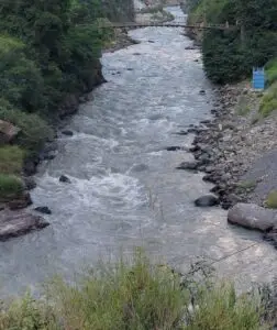
Every hydropower plant begins with a river, stream or reservoir. The catchment area — the geographic region that collects rainfall and snowmelt feeding the river — determines the total water available for generation. Larger catchments with higher rainfall and snowmelt produce more consistent water flow and therefore more reliable generation. Pakistan’s major hydel plants on the Indus, Jhelum and Kabul rivers benefit from enormous Himalayan and Karakoram catchments fed by some of the world’s largest glaciers. The seasonal variation in catchment output — high flows during summer snowmelt, lower flows in winter — directly determines hydel generation patterns throughout the year.
2. The Dam or Weir — Creating the Head
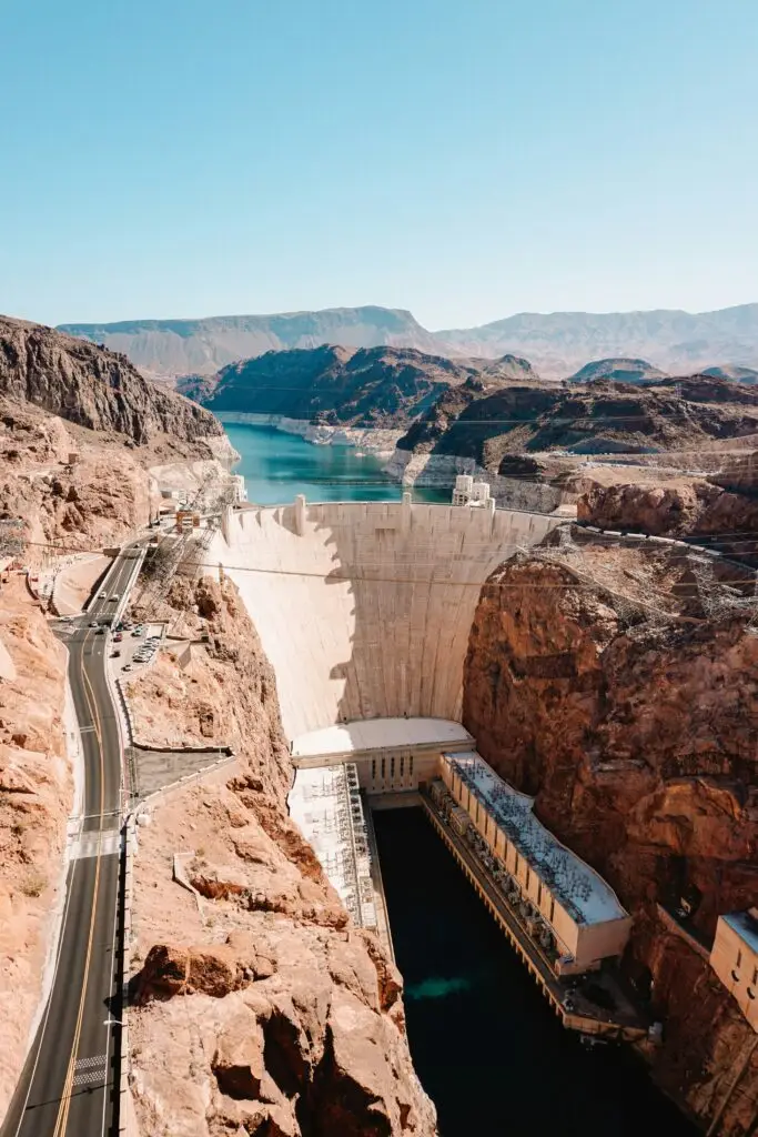
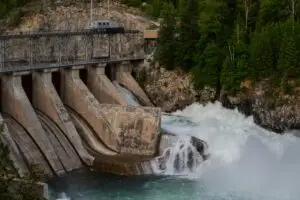
Photo by Emily-Jo Sutcliffe on Unsplash
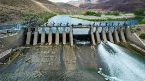
The dam or weir is the civil structure that creates the hydraulic head — the difference in water level between the upstream reservoir and the downstream tailrace. Head is the single most important parameter in hydropower generation. The higher the head, the more potential energy available per unit of water flow.
A plant with 100 metres of head generates significantly more power from the same water flow than a plant with 20 metres of head. This is why high head sites in mountainous regions like KPK, Gilgit-Baltistan, Nepal and Bhutan are so valuable for hydel development. Storage dams — like Tarbelahttps://en.wikipedia.org/wiki/Tarbela_Dam and Mangla https://en.wikipedia.org/wiki/Mangla_Dam— create large reservoirs that store water during high flow seasons for controlled release during low flow periods. Run of river weirs — like those at Dargai and Warsak — divert river flow into a canal or tunnel without significant storage, generating power continuously from natural river flow.
3. The Intake and Trash Rack
The intake is the structure that controls water entry into the hydropower system from the reservoir or river. A properly designed intake ensures smooth, controlled water flow into the conveyance system while preventing debris, sediment and foreign objects from entering and damaging downstream equipment.
The trash rack — a series of metal bars or screens installed at the intake — filters out floating debris, logs, vegetation and large objects that would otherwise damage turbine components. In my field experience, blocked or damaged trash racks are among the most common causes of unplanned generation outages. Regular cleaning and inspection of trash racks is a critical O&M activity on every hydel plant. Intake gates — large steel structures operated by hydraulic or mechanical systems — control water flow into the system and allow complete isolation of the waterway for maintenance and emergency situations.
4. The Headrace — Tunnel or Canal
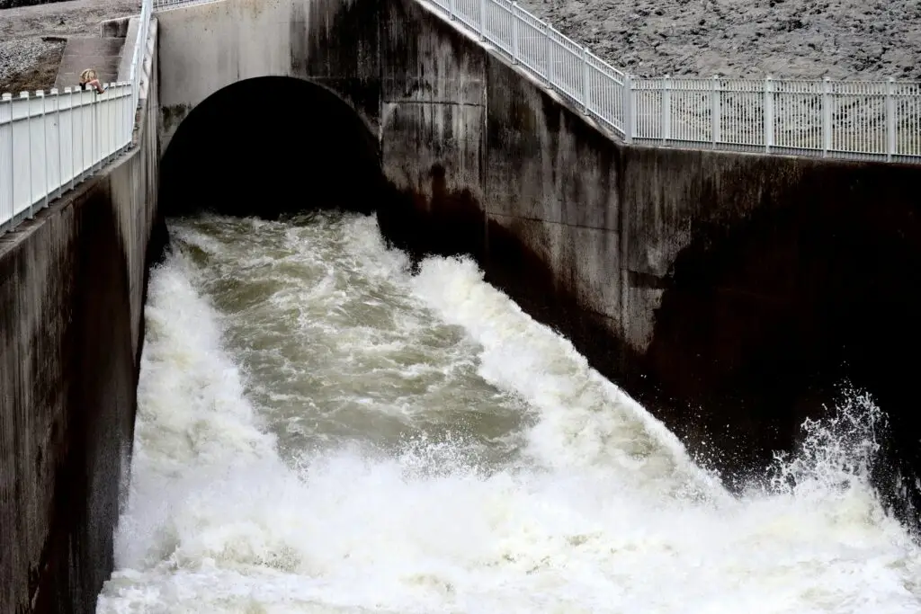
Photo by Rebecca Johnsen on Unsplash
The headrace is the conveyance system that carries water from the intake to the turbine. In run of river plants it is typically an open canal or covered flume running along the hillside following a gentle gradient. In high head mountain projects it is usually a pressure tunnel bored through rock — sometimes kilometres long — carrying water under pressure from the intake to the powerhouse. Headrace tunnels on major hydel projects are engineering marvels in themselves.
The Neelum Jhelum Hydropower Project in AJK has a headrace tunnel system of approximately 68 kilometres — one of the longest in the world. Tunnel construction through complex Himalayan geology involves some of the most challenging engineering work in the hydel sector. Rock conditions, water ingress, fault zones and seismic activity all present significant construction and operational challenges. At the end of the headrace — just before the turbine — sits the forebay or surge shaft, a chamber that absorbs pressure fluctuations when turbine load changes suddenly, protecting the entire waterway system from damaging water hammer effects.
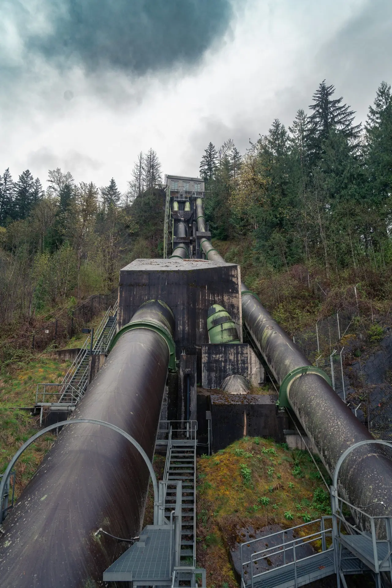
5. The Penstock — The High Pressure Pipeline
The penstock is the high pressure steel pipeline that carries water from the forebay or surge shaft directly to the turbine inlet. It is one of the most critical and technically demanding components in the entire hydropower system. Penstocks operate under enormous pressure — the full hydraulic head of the plant bears down on the penstock walls with every metre of vertical drop. A penstock serving a 500 metre head plant must withstand pressures equivalent to 50 atmospheres continuously for decades. Steel thickness, weld quality, expansion joints, anchor blocks and support structures must all be engineered precisely for the specific head, flow and geology of each project. Penstock failures — though rare on well designed and maintained plants — are catastrophic events.
A penstock rupture under full operating pressure releases an uncontrollable high velocity water jet capable of destroying everything in its path. In my field experience, penstock inspection, pressure testing and maintenance scheduling are among the highest priority activities on any hydel plant. The penstock is where the enormous energy stored in the reservoir is finally concentrated into a focused, controllable flow ready to drive the turbine.
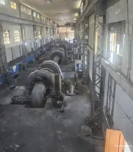
6. The Turbine — Converting Water Energy to Mechanical Energy
The turbine is the heart of every hydropower plant — the component where water energy is converted into mechanical rotational energy. Water strikes the turbine runner with enormous force, causing it to spin at high speed. This rotation is transmitted through the turbine shaft directly to the generator above. Different turbine types are used depending on the head and flow characteristics of each site. Pelton turbines — used at very high head, lower flow sites — use jet nozzles to direct high velocity water streams onto cup shaped buckets around the runner periphery. Francis turbines — the most widely used type globally — handle medium to high head sites and are found in most of Pakistan’s major hydel plants including Tarbela, Mangla and Ghazi Barotha. Kaplan turbines — used at low head, high flow sites — have adjustable blades that optimize efficiency across varying flow conditions.
Turbine selection, design, manufacturing quality and installation precision directly determine plant efficiency and long term reliability. In my experience, turbine installation and alignment is one of the most technically demanding phases of hydel plant commissioning — tolerances measured in fractions of a millimetre on components weighing hundreds of tonnes.
7. The Generator — Converting Mechanical Energy to Electricity
The generator is directly coupled to the turbine shaft — as the turbine spins, the generator produces electricity. Hydro generators are synchronous machines — they produce alternating current at a frequency precisely determined by their rotational speed and number of poles. In Pakistan’s 50Hz grid, generators must rotate at exact synchronous speed — 500 RPM for a 12 pole machine, 333 RPM for an 18 pole machine — to produce electricity at the correct frequency.
The generator consists of two main components — the rotor and the stator. The rotor — attached to the turbine shaft — carries the field winding energized by DC excitation current, creating a rotating magnetic field. The stator — the stationary outer component — carries the armature winding where the rotating magnetic field induces the three phase AC output voltage. Hydro generators are among the largest rotating electrical machines ever built. A single generating unit at Tarbela Dam weighs thousands of tonnes, stands several storeys tall and produces hundreds of megawatts of electricity from a single shaft. Witnessing the first rotation of a newly commissioned hydro generator — a structure of that scale moving with absolute precision — is one of the most impressive experiences in engineering.
8. The Transformer and Switchyard — Stepping Up For Transmission
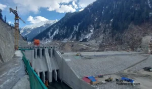
Electricity generated by the hydro generator exits at medium voltage — typically 11kV to 15kV depending on plant design. This voltage is too low for efficient long distance transmission to load centers. The main power transformer — connected directly to the generator terminals — steps up this voltage to transmission level — typically 132kV, 220kV or 500kV depending on the plant capacity and grid connection requirements. Higher voltage means lower current for the same power — dramatically reducing transmission losses over long distances. From the transformer the electricity enters the switchyard — an outdoor or GIS indoor facility containing circuit breakers, disconnect switches, current transformers, voltage transformers, surge arresters and busbar systems.
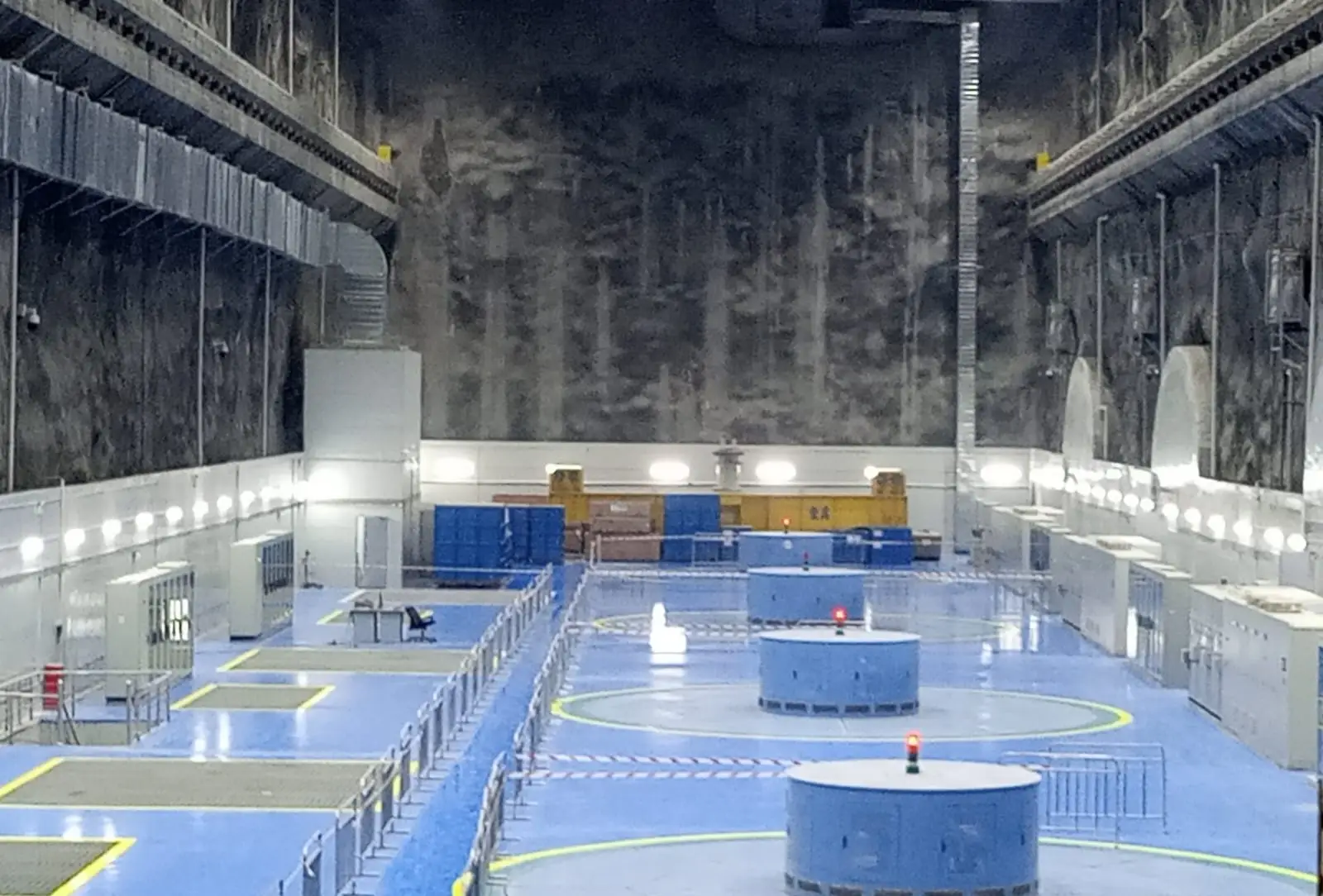
The switchyard is where the plant connects to the national grid transmission system. Protection relays in the switchyard monitor all electrical parameters continuously — detecting faults and isolating the plant from the grid within milliseconds when abnormal conditions occur. The GIS — Gas Insulated Switchgear — hall visible in our site photos represents the most modern switchyard technology — all high voltage equipment enclosed in SF6 gas insulated metal enclosures, dramatically reducing the physical footprint compared to conventional outdoor switchyards while improving reliability and safety.
9. The Control System — The Brain of the Plant
Every modern hydropower plant is controlled by a sophisticated digital control system — the plant’s brain. The Unit Control Board and Central Control Room house the SCADA — Supervisory Control and Data Acquisition — system that monitors and controls every aspect of plant operation in real time. From the control room operators monitor turbine speed, generator output, transformer temperatures, switchyard status, reservoir levels, penstock pressure, bearing temperatures and hundreds of other parameters simultaneously. Automatic protection systems operate independently of operator input — detecting abnormal conditions and executing protective actions in milliseconds.
If a generator bearing temperature rises beyond safe limits, the protection system automatically shuts down that unit before damage occurs. If a penstock pressure surge exceeds design limits, pressure relief valves operate automatically. Modern hydel plants increasingly use remote monitoring and control systems — allowing operators at a central dispatch center to monitor and control multiple plants simultaneously. AI based predictive maintenance systems are now being integrated into hydel plant control systems globally — analyzing operational data patterns to predict equipment failures before they occur, reducing unplanned outages and maintenance costs significantly.
10. The Tailrace — Completing the Water Cycle
After passing through the turbine and giving up its energy, water exits through the draft tube into the tailrace — the channel or tunnel that returns water to the river downstream of the dam. The draft tube is a carefully engineered diverging passage that recovers residual kinetic energy from the water leaving the turbine runner, improving overall plant efficiency. The tailrace must be designed to handle the full plant discharge without causing backpressure on the turbines — excessive tailrace water levels reduce the effective head across the turbine and reduce generation output.
On underground powerhouse projects the tailrace tunnel can be kilometres long, carrying discharge water through the mountain back to the river at a suitable downstream location. The point where tailrace water re-enters the river is called the outfall. Environmental flow requirements — minimum water flows that must be maintained in the river between the dam and the tailrace outfall — are now standard conditions on all hydel project licenses. This environmental flow sustains river ecosystems in the dewatered reach between dam and outfall, one of the key environmental mitigation measures on modern hydel projects.
How Hydropower Plants Work — Field Engineer’s Perspective
Understanding how hydropower plants work from a textbook is one thing. Standing inside an operating plant and experiencing it is something entirely different. The moment a hydel unit synchronizes to the grid for the first time — after months of civil construction, mechanical installation, electrical termination and commissioning testing — every component in this entire chain works together simultaneously for the first time. Water flows from the reservoir through the intake, down the penstock, through the turbine, into the generator, through the transformer, into the switchyard and onto the national grid — all within seconds of the synchronization command. The turbine runner spinning at synchronous speed with tolerances of fractions of a millimetre. The generator producing three phase electricity at precisely 50Hz. The protection systems monitoring every parameter in real time. The control system coordinating every action automatically.
In 15 years of working on hydel projects — from small run of river schemes in KPK to large underground powerhouse projects — that moment of first synchronization never loses its impact. It is the culmination of years of engineering work by hundreds of people — civil engineers, mechanical engineers, electrical engineers, protection engineers, control system engineers, commissioning teams — all coming together in one instant. That is how hydropower plants work. Not just as a chain of components — but as a precisely coordinated engineering system where every element must perform perfectly for the whole to function.
Conclusion — From Water to Electricity in Ten Steps
How do hydropower plants work? Water from a catchment area is impounded by a dam or diverted by a weir — creating hydraulic head. That water flows through an intake past trash racks into a headrace canal or tunnel. It enters a forebay or surge shaft before accelerating down a high pressure penstock. It strikes a turbine runner — Pelton, Francis or Kaplan depending on head and flow — converting water energy into mechanical rotation.
The rotating shaft drives a synchronous generator producing three phase AC electricity. A main power transformer steps up the voltage for efficient transmission. The switchyard connects the plant to the national grid through circuit breakers and protection systems. A sophisticated control system monitors and manages every parameter in real time. The water exits through the draft tube and tailrace returning to the river to continue its natural cycle. Ten steps.
One seamless system. Clean renewable electricity for generations. Hydropower is not complicated in principle — it is demanding in engineering execution. Getting every one of those ten steps right — in design, construction, installation, commissioning and operation — is what separates a reliable long term hydel asset from an expensive problem. That engineering excellence is what this platform is about.
For more field tested hydel knowledge explore our complete guides on What Does Hydel Mean,Home Hydel Power Advantages and DisadvantagesBlog and Is Hydel Energy Renewable.Blog