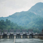
Spillways in Hydropower: Purpose and Necessities
In February 2017, a crater opened in the concrete chute of the Oroville Dam spillway in California — the tallest dam in the United States. Within days, engineers were forced to run water down an unlined emergency spillway that had never been used at full flow in the dam’s 48-year history. It eroded almost immediately, threatening to undercut the structure and triggering the evacuation of 188,000 people downstream. The dam itself never failed. The spillway did. That distinction is the entire reason spillways deserve as much engineering attention as the dam they sit beside.
What a spillway actually does
A dam’s job is to hold water back. A spillway’s job is to let it go — safely, in the one scenario the dam was never designed to survive on its own: a flood bigger than the reservoir can store.
Every reservoir has a design flood, usually the Probable Maximum Flood (PMF) or a flood of a specified return period (1-in-1,000 year, 1-in-10,000 year, depending on the dam’s hazard classification). If that flood arrives and there is nowhere for the excess water to go, it goes over the top of the dam. For an embankment dam built from earth and rock, overtopping is almost always fatal — the downstream face erodes, the crest breaches, and the failure is often complete within hours. Concrete gravity and arch dams tolerate overtopping better, but not indefinitely, and not with the intake, powerhouse, and downstream infrastructure still standing.
The spillway exists to make sure that scenario never happens. It is not an optional extra bolted onto the dam — for most large dams, sizing and locating the spillway is the single decision that governs how big and how expensive the whole project becomes.
Sizing: the design flood problem
Spillway capacity is set by hydrology, not by turbine flow. A run-of-river plant might pass 200 m³/s through its turbines on an average day and need a spillway capable of passing 8,000 m³/s or more during an extreme flood. That gap is the whole design problem.
Three numbers drive the sizing exercise:
- Inflow design flood (IDF) — the flood the spillway must pass without overtopping the dam, derived from the PMF or a statistical return-period flood, adjusted for the dam’s hazard classification (loss of life and downstream damage potential if it fails).
- Reservoir routing — how much of that inflow the reservoir itself can absorb by rising within its surcharge storage before the spillway needs to be discharging at full capacity. A reservoir with a large surface area and available freeboard can shave a significant fraction off the peak outflow the spillway must handle.
- Freeboard — the vertical gap between maximum reservoir level during the design flood and the dam crest, which has to absorb wind-generated wave run-up on top of the flood surcharge.
Undersizing any of these was the root of Oroville. The flood that damaged the main spillway wasn’t extreme — the gated spillway was operating well within its rated capacity when the crater opened. The failure was a construction defect: a slab built over an unlined, ungrouted foundation with inadequate drainage, so that water intruded beneath the concrete and uplift pressure did the rest. The lesson field engineers took from it wasn’t about hydrology — it was that the emergency spillway, an unlined hillside that had sat untested for half a century, was never actually validated as a spillway. It was a design on paper that had never seen water.
Types of spillway
Overflow (ogee) spillway
the classic curved profile on a concrete gravity dam, shaped to match the underside of a free-falling jet so the water stays in contact with the surface at design flow, avoiding negative pressure and cavitation. Simple, self-regulating if ungated, and the default choice where the dam itself is concrete.
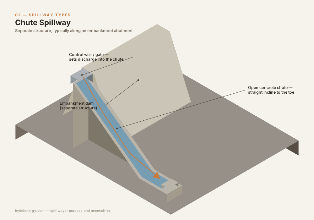
Chute spillway
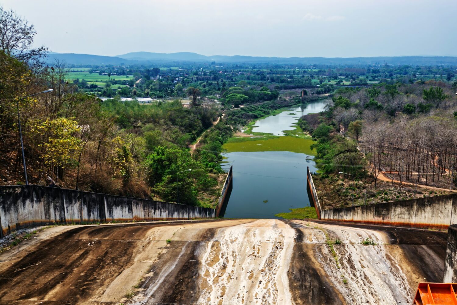
used on embankment dams where the spillway can’t be cut into the dam body itself. Water is carried away from the reservoir in a straight or curved open channel, usually along one abutment, down to a stilling basin. This is what failed at Oroville — the failure mode field engineers now watch for is exactly the one that occurred there: sub-slab drainage and foundation condition, not just hydraulic capacity.
Side channel spillway
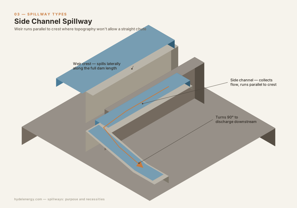
water spills laterally over a weir into a channel running parallel to the dam crest, then turns to discharge downstream. Used where topography doesn’t allow a straight chute.
Shaft (morning glory) spillway
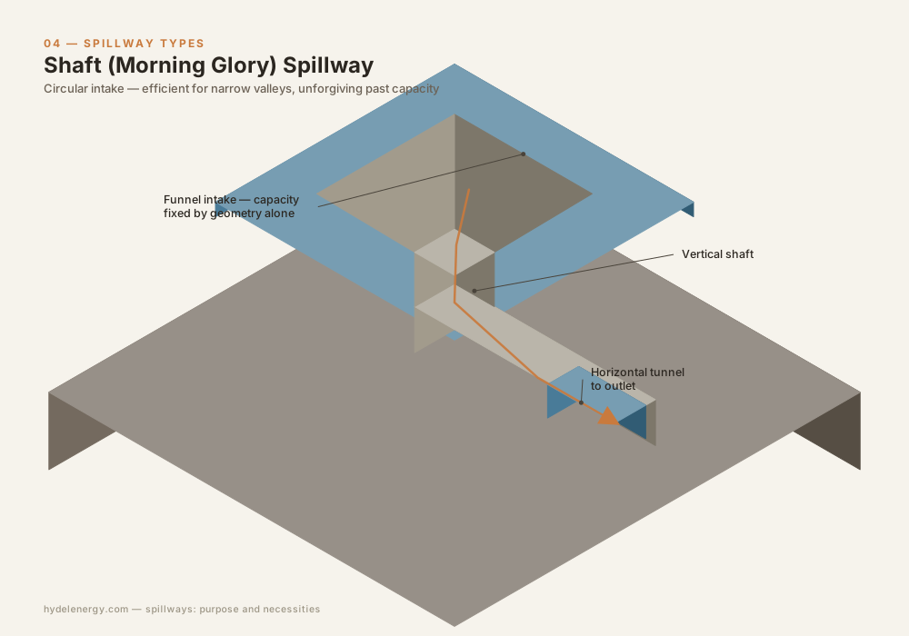
a circular intake dropping into a vertical or inclined shaft, then a horizontal tunnel to outlet. Efficient for narrow valleys with limited space for a surface spillway, but unforgiving: capacity is fixed by the geometry of the intake, and once the shaft is running full, further inflow simply overtops the reservoir. Monticello Dam in California is the reference case everyone in the field learns from — spectacular to watch, exact opposite of forgiving if the design flood is exceeded.
Siphon spillway
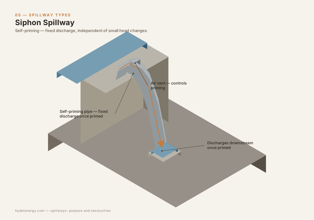
self-priming, discharges at a fixed rate once primed regardless of small head changes, useful for tight water-level control. Rare on large hydropower schemes because of maintenance complexity and vulnerability to debris, but still specified on some run-of-river weirs.
Gated vs. ungated
An ungated (free) spillway crest starts passing water automatically once the reservoir reaches crest level — no operator action required, no mechanical failure possible, but it means the reservoir can never be drawn down above crest level for extra storage, and peak discharge is entirely a function of reservoir level.
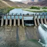
A gated spillway (radial/Tainter gates are the standard choice on large dams) allows the crest to sit below normal reservoir level, recovering active storage, and gives operators control over the timing and rate of release — useful for flood routing and for coordinating with downstream conditions. The cost is that gates are mechanical equipment: they need power, they need maintenance, and they need to work under emergency conditions after possibly years of sitting idle. Gate failure during a flood event — hydraulic ram seizure, power loss to hoists, debris jamming a slot — is a standing item on every dam safety inspection checklist for exactly this reason. Standard practice is to size the spillway so the design flood can still be passed with one gate assumed inoperable.
Energy dissipation
None of the above matters if the water arriving at the toe of the spillway is left to do what a few hundred cubic metres per second of high-velocity water naturally does to unprotected riverbed and foundation material — scour it out from underneath the structure. Dissipating the kinetic energy before the flow re-enters the river is as much a part of spillway design as the crest and chute.
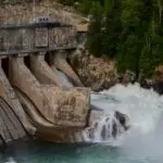
- Stilling basins use a hydraulic jump — the flow transitions from supercritical to subcritical, converting velocity into turbulence and heat — inside a concrete apron with baffle blocks and an end sill to hold the jump in place across the operating flow range.
- Flip buckets (ski-jump spillways) throw the jet clear of the dam toe entirely, letting it dissipate energy in the air and plunge into a downstream pool or pre-formed scour hole, common where the foundation rock is competent enough to accept localized scour without endangering the structure.
- Roller buckets are a shorter-radius variant used where space is limited, producing a submerged hydraulic roller rather than a free jet.
Cavitation is the recurring failure mode across all of these. Any irregularity in the chute surface — a misaligned joint, a repair patch, debris impact damage — creates a low-pressure zone downstream of the irregularity at high velocity, and vapor bubbles collapsing against concrete will erode a chute surface in hours during a major flood event, not years. Chute surface tolerances on major spillways are specified in millimetres for exactly this reason, and post-flood inspection of the chute surface is standard practice after any high-flow event, regardless of whether anything looked wrong from the control room.
Why this belongs in commissioning and O&M, not just design
A spillway is unusual among hydropower structures in that it can sit for years, even decades, without passing a meaningful flow — and then be asked, with no warning, to perform at its absolute design limit on the first real test it has ever faced. Turbines run every day and reveal problems early. Spillways often don’t get that luxury. That asymmetry is why dam safety programs treat spillway inspection, gate testing, and PMF re-assessment (as rainfall data and climate patterns shift) as a recurring discipline rather than a design-phase checkbox — and it’s the single biggest reason Oroville, despite happening to one of the tallest dams in the country, surprised almost no one who had spent time around aging spillway infrastructure.
Turbine Selection Chart — Head vs Flow Calculator | Hydel Energy What “Water to Wire” Actually Includes — And What It Doesn’t Ongoing Hydel (Hydropower) Projects in Nepal — Upper Tamakoshi, Upper Karnali and the Road Ahead